The current situation of the German government appears to be a state of desolation: The constitutional court did not play along as hoped – albeit by the narrowest of margins – and has awarded the Ampel Coalition a 60-billion-euro gap in the budget.
Out of this, a desolate situation for the energy industry could also rise, since many projects that were to be financed via the planned fund for climate action and clean energy Klima- und Transformationsfonds (KTF) have come into question, justifiably or not. The uncertainty is great.
Advertisements
The situation beforehand was already tense. Decisions from Brussels, for example, have had a long wait time. This was the case with the EU energy directive RED II, RED III and also the IPCEI projects – even though RED III was published on October 31, 2023. If things go well, at the end of the year still, the 37th ordinance on the implementation of the German emissions reduction act (37th BImSchV) could be updated – after twelve years.
This waiting has not exactly encouraged many investors to make their money available for projects for the future. The FID (final investment decision) especially for numerous electrolysis projects is still pending, because the framework conditions are not seen as sufficiently secure.
Not without reason, numerous companies took part in the tender for the Important Projects of Common European Interest. In doing so, they are relying on EU member state funds to reduce their own financial risk.
The price they have to pay for these “gifted” state funds is that they have to abide by the giver’s rules. It also means that they have to put up with it when a decision takes longer in Brussels.
The loud lamentation therefore has a bit of hypocrisy to it, since after all nobody forced them to apply for an IPCEI. They could all have started much earlier on such projects, even at their own risk. But now some of them are sitting there complaining that their originally planned IPCEI project is no longer viable in the form applied for, although it was they themselves who had decided to take this path.
Again and again in this context have there been warnings that companies based in Germany could move abroad to where the framework conditions are supposedly better. Perhaps there are individual companies that will actually take this step. Exactly what their motives are, we will probably never know, but it should be clear that such a decision does not depend solely on the processing time in Brussels but is multifactorial.
And yes, one or two projects will probably never be realized – for whatever reason. Westküste100 is such a project. As a real-world lab it has done valuable work, but “H2 Westküste GmbH will not make a positive investment decision for the planned electrolyzer” can be read on their homepage. And “The reason for it is especially the increased investment costs.”
That may hurt one or the other player, since such a scenario may also threaten other projects. But isn’t it better to stop a recognizably uneconomical project at the right time than to desperately hold on to it and to go through with it against your better judgment? Isn’t it better to acknowledge the altered framework conditions by the now two wars and current energy emergency, and to recalculate?
Because Westküste100 won’t continue does not mean that the energy transition has been canceled, that we are not switching to renewable energies and hydrogen after all. Just because a few companies will produce elsewhere in the future does not mean that value creation will no longer take place in Germany.
The political commitment is there: German economy minister Robert Habeck as well as numerous minister-presidents of the federal states recently emphasized the enormous importance of H2 projects in particular. In addition, a startup scene has now established itself in Germany, which is pushing its way onto the market with new, innovative ideas. Here, investors are called to recognize their potential and make advance investments now at their own risk – without subsidies.
I don’t want to refer to the American e-car manufacturer again, but there exist – even in Europe – players who with a little instinct or a lot of money can make new technologies marketable at the right time.
The energy transition is a gigantic challenge – for everyone. Who, if not Germany, would be better placed to exemplarily show the way and offer suitable products? Instead of seeing the enormous potential that lies in this global upheaval, however, many in this country remain stuck in “German Angst.” It’s bad enough that this term (according to Wikipedia, “typical German hesitancy”) is now commonplace around the world.
The motto should therefore be: “Recognize and leverage potentials to shape a sustainable future together.”
Effective and efficient cleaning of metal bipolar plates
Low weight and volume, good cold-start capability and relatively inexpensive series production are all benefits associated with metal bipolar plates. These key elements in fuel cell stacks are responsible for handling the essential tasks of supplying media, creating an electrical connection and cooling. Their ability to perform these well depends on factors such as the cleanliness of both the material and the joined plate. Ecoclean has trialed a variety of processes to find the most effective and economical method of cleaning.
Advertisements
Fuel cells are among the key technologies for enabling the electrification of vehicle propulsion systems and also have a major part to play in the energy transition as a stationary energy source. At the heart of a fuel cell system are the bipolar plates or BPPs that are connected to the stacks. BPPs consist of an anode and a cathode with a proton-conducting film sandwiched between them.
BPPs fulfill a variety of tasks: They physically and electrically connect the anode of a cell to the cathode of the neighboring cell. They are also responsible for conveying the reactant gases – hydrogen on the anode side and air on the cathode side. For this purpose, the plates are designed with flow fields on both sides whose form is crucial for the performance of the overall system. In addition, the BPPs control the release of electrical energy and the removal of water vapor. Another function they perform is the management of heat.
Plates can be manufactured from different materials: high-concentration graphite, graphite-polymer composites and metals. Metal bipolar plates offer advantages particularly when it comes to their use in automobiles. This is because they are low in weight and volume and have a good cold-start capability. What’s more, metal BPPs offer the potential for comparatively cost-effective series production which can be further improved through scaling.
Clean for quality and efficiency
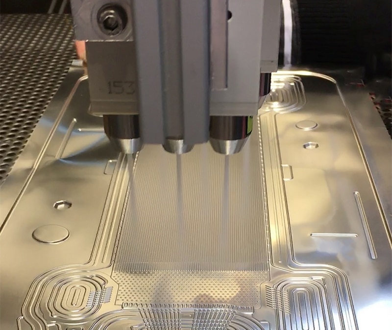
The anode and cathode of metal BPPs are predominantly made from stainless steel alloy foils with a thickness of 0.1 mm to 0.2 mm. The material is usually rolled off a coil whose surfaces are contaminated during manufacturing by different rolling and drawing greases, oils, emulsions and other unknown impurities. In the next step, the anode and cathode foils are precisely reshaped in a mechanical or hydroforming process and the outer contours are cut, for instance, by punching or laser cutting.
Residual machining fluids (oils and/or emulsions) are also left on the plates following these processes. When the anode plate and cathode plate are subsequently joined, commonly in a laser welding process, this results in smoke residue and oxide being left behind. Finally, the bipolar plates are coated. A cleaning stage must be performed prior to the plates being coated, if not earlier, to ensure a homogeneous coating with good adhesion.
For tightly packed fuel cells, which are required to achieve a high output in minimal space, it is recommended that cleaning takes place before the joining stage. This prevents impurities becoming trapped between the anode and cathode which can become loose when the temperature rises during operation and block the microstructures of the flow fields. This would lead to a decrease in performance. At the same time, the intermediate cleaning stage will reduce the surface contamination from smoke residue and oxides during the laser welding process.
Choosing the right process
A key challenge in cleaning metal BPPs is the presence of usually invisible chemical film residue on the surfaces. This may be oils, greases, emulsions or other chemicals that are often of unknown composition. These unidentified contaminants require a cleaning solution that ensures they are removed reliably and appropriately. This is why German company Ecoclean has carried out experiments using laser and carbon dioxide snow-jet cleaning, wet-chemical solvent cleaning as well as steam-jet cleaning.
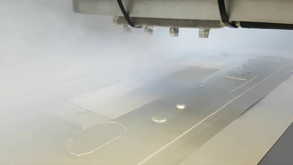
Fig. 2: Steam cleaning works due to a combination of steam, a precise quantity of fluid for the job, high-speed air flow and an adapted nozzle system
Both the laser and carbon dioxide snow-jet methods effectively removed smoke residue, oxide, chemical film contamination and particles from the welded seams of the joined bipolar plates with pin-point precision and within a matter of seconds. Good results were also recorded for both processes when cleaning whole BPP surfaces. Because the laser has to travel over the surface line by line, this option is time consuming. In the case of carbon dioxide snow-jet cleaning, the system can be fitted with an appropriate number of nozzles, thereby allowing for rapid treatment of the entire surface.
Wet-chemical cleaning with solvent using a flood method was able to successfully remove oils, greases and particles. However, it is not suitable for cleaning off emulsions, smoke residue and oxides. Wet-chemical immersion cleaning with water-based media is only possible to a limited degree due to the drying required and the considerable effort involved.
Good results were also achieved when using steam jets to clean chemical film and particulate contamination as well as smoke residue and oxides. For this process, the cleaning effect comes from a combination of steam, a precise quantity of fluid for the job, high-speed air flow and an adapted nozzle design. The cleaning procedure also takes just a few seconds.
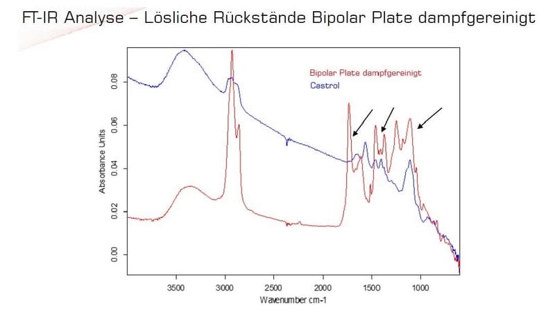
Fig. 3: Analysis from infrared spectroscopy showed that steam cleaning completely removed the residue of the reference contamination
Controlled cleaning validation
Cleaning results are verified using the surface tension through the measuring techniques of contact angle measurement and test inks, fluorescence measurement and infrared spectroscopy. The fluorescence measuring technique proved to be unsuitable due to the absence of fluorescent contaminants. In terms of the input measurements for surface tension, the bipolar plates produced very different contamination values which were significantly reduced after cleaning.
A general statement about whether the component has a sufficient level of cleanliness for the next processing step cannot be made. For this to be possible, it would be necessary to determine appropriate process-specific requirements. For infrared spectroscopy, all residue on the test pieces (coil sections and BPPs) was first removed to establish a reference cleanliness. After the surfaces of the test pieces were analyzed using infrared spectroscopy, the test pieces were contaminated with reference contamination before being cleaned and then reanalyzed. This analysis then showed that steam cleaning managed to reliably remove chemical film contamination.
The cleaning trials and tests outlined were carried out in Ecoclean’s test center in Monschau by experts in component cleaning and surface treatment using the methods described as well as other techniques.
Automated cleaning
For an efficient workflow, it is possible for cleaning to be integrated prior to joining and/or coating in production lines. Automation can be adapted and optimized to suit the specific requirements and conditions of each production line.
Ecoclean is part of the SBS Ecoclean Group which develops, produces and distributes cutting-edge equipment, systems and services for industrial component cleaning and surface treatment. Its solutions help companies around the world from the automotive and supply industries as well as the highly diversified industrial market to implement efficient and sustainable production processes. The group has an international presence with 12 sites in nine countries and employs more than 900 staff.
Doubling the distance with a fuel cell range extender
An electric moped with a 150-kilometer (90-mile) range that refuels in under a minute? With a fuel cell and hydrogen tank acting as a range extender, it is feasibly possible. Confirmation of this can be found in a joint study entitled “Pocket Rocket H2” that has been undertaken by DHBW university and SOL Motors in Böblingen, Germany.
Advertisements
Electric bikes and e-scooters have already become part of the urban landscape. Now mopeds are edging into electric propulsion. In fall this year, the eye-catching Pocket Rocket from startup SOL Motors is being launched on the market.
The battery electric model is available in two versions with maximum speeds of 45 km/h (28 mph) or 80 km/h (50 mph). In both cases, the range is between 50 and 80 kilometers (30 and 50 miles) and it takes around three hours for the battery to recharge from a domestic socket. This is usually entirely sufficient for riding the Pocket Rocket on the daily commute to work.
Nevertheless, there are also circumstances where a rider will want to recharge rapidly and travel further. For example, the use of mopeds can be envisaged in disaster response situations where a greater range will be needed along with continuous availability. Conditions that can be met by a fuel cell vehicle.
Electric vehicles: battery or fuel cell?
At the moment, the vast majority of electric vehicles around the world, from e-scooters to light commercial vehicles, are powered by batteries. A fuel cell only comes into play if higher power outputs and large amounts of energy are demanded. Typical examples are heavy-duty vehicles, trains, ships or airplanes. Because the hydrogen tank and the fuel cell are separate, this means that the amount of energy and the power output are decoupled in a fuel cell power system. This gives a higher degree of freedom in terms of the system layout, including for smaller vehicles.
A fuel cell power system cannot dispense with a battery completely since it is needed for starting the system and for regeneration. There are various ways to configure the battery in combination with the fuel cell: If the entire driving power is provided by the battery, the fuel cell acts only as a range extender. Almost the reverse of this would be the option whereby propulsion would be provided purely by the fuel cell and a small starter battery would be used that can temporarily store the braking energy. If both power sources work together, this is called hybrid operation.
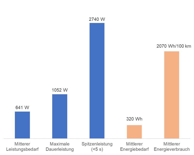
Consequently, the Pocket Rocket H2 project focused initially on the issue of configuration since comparable vehicles are not (yet) on the market. The starting point for calculations was the test cycle defined in the Worldwide Harmonised Light Vehicle Test Procedure or WLTP which, together with the vehicle data for the Pocket Rocket (version with maximum 45 km/h), supplies the power and energy from fig. 2. As a result, the decision was made to opt for a fuel cell as a range extender.
Fig. 2: Calculated power and energy requirement of the Pocket Rocket (version with max. 45 km/h) from the WLTP test cycle
Benefits of a fuel cell range extender
When a fuel cell is used as a range extender, its purpose is merely to recharge the battery. Therefore very little has to be done to the battery electric vehicle’s control system. In its capacity as a range extender, the fuel cell only has to supply a power output of up to 1,000 watts; peak loads are covered by the battery. The range, meanwhile, is limited only by the size of the hydrogen tank. For fuel cells in the performance class up to 1,000 watts, simple air cooling is sufficient; from around 2.5 kilowatts upward, a more complex water cooling system is needed. As a range extender, the fuel cell can be operated at constant power while also protecting the battery from exhaustive discharge. Both factors increase the life of these components.
The only disadvantage of the chosen configuration is that the battery has to be large enough to ensure several kilometers can be covered with a power output over 1,000 watts, e.g. for mountain driving.
Demonstrator in the lab
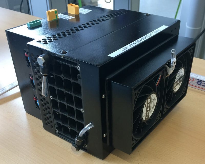
As part of the project, the system comprising the battery and fuel cell range extender was set up as a lab prototype. For this purpose, a proton exchange membrane or PEM fuel cell system from Hydrogen Air Technologies was used (see fig. 3).
Fig. 3: Compact fuel cell system with a 1,000-watt continuous output. The fans for air cooling can be seen in the right of the picture. The hose between the fans is used for nitrogen purging.
The system with its 65 cells is air-cooled by means of simple, speed-controlled fans and supplies the described maximum electrical output of 1,000 watts. The voltage varies, depending on the output level, between 65 volts (idling) and 35 volts (maximum power). The setup is known as a dead-end system, in other words only the amount of hydrogen that will be consumed is supplied.
In the dead-end system, nitrogen accumulates relatively quickly on the hydrogen side (anode) due to diffusion. This nitrogen must then be released via a purging valve. Purging lowers the efficiency of the system as it also carries away unused hydrogen. The fuel cell system under investigation has an efficiency of around 35 percent at 1,000 watts. Converted into hydrogen consumption, this is equivalent to 85 grams of hydrogen an hour.
Electrical connection
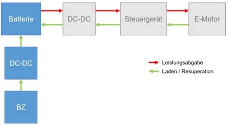
The use of the fuel cell system as a range extender results in an extremely simple electrical connection. As illustrated in fig. 4, a DC-DC converter has to adjust the output voltage of the fuel cell to the end-of-charge voltage of the battery. The battery can then be continuously charged at a constant voltage. The fuel cell controller adjusts its output power to the prevailing charging current. The powertrain control unit remains unaffected by the charging carried out by the fuel cell.
Fig. 4: Connection of electrical components of the fuel cell when used as a range extender
Thanks to the fuel cell system, the battery can be reduced from 2.5 kilowatt-hours to 0.35 kilowatt-hours while retaining the same motor output. In principle, the range can then only be limited by the tank volume, in other words the quantity of hydrogen in the tank. The power requirement ascertained by the WLTP test cycle produces, together with the system efficiency, a hydrogen consumption of approximately 200 grams for 100 kilometers (60 miles). This means that the fuel cell version of the Pocket Rocket could travel a distance of 500 kilometers (300 miles) on 1 kilogram of hydrogen!
Concern about pressurized hydrogen tanks
Unfortunately, the storage of hydrogen for motive applications is still unsatisfactory. Hydrogen is around 14 times lighter than air. It therefore has to be compressed in order to store the gas in significant quantities. But even at a pressure of 700 bar, 1 kilogram of hydrogen takes up a volume of almost 40 liters. In addition, a pressurized tank of 700 bar, which stores 1 kilogram of hydrogen, weighs about 24 kilograms. This makes it even more remarkable that the Pocket Rocket H2 is only around 2 kilograms heavier than the battery electric vehicle – and has twice the range.
By reducing the battery from 2.5 kilowatt-hours to 0.35 kilowatt-hours, its weight decreases from roughly 14 kilograms to just around 2 kilograms. In total this works out at around 16 kilograms which is spread across the fuel cell (4 kg), tank (9 kg), battery (2 kg) and other components (1 kg) such as the DC-DC chopper and connectors. The pressurized hydrogen tank is not only the largest component; it is also the heaviest. This is principally due to the high safety requirements for use in road transportation.
These days, high-pressure tanks for hydrogen consist of a polymer liner wrapped in carbon fibers that have been impregnated with epoxy resin. The carbon-fiber layer is several centimeters thick to ensure the desired requirements are met, for instance a burst pressure of 2.35 times the working pressure. Thus only round or cylindrical tanks can be produced for manufacturing reasons. To house the tank on the frame of the Pocket Rocket, more flexible tank geometries would be desirable, though these would exceed all budgets at this point in time.
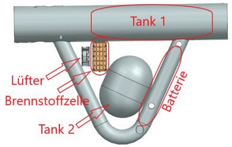
In the final part of the project, options for housing the components of the range extender on the frame of the Pocket Rocket were explored in a CAD model (see fig. 5).
Fig. 5: Research into the arrangement of individual components of the fuel cell range extender on the frame of the Pocket Rocket H2. The pressurized hydrogen tanks take up the most space.
The battery, which in the battery electric model is located in the upper cross tube, is now much smaller and could migrate into one of the V tubes. In this version, hydrogen would be stored in two tanks, both in the cross tube and in a separate tank. Admittedly, the upper tank on its own would be capable of storing almost all the 350 grams of hydrogen needed to double the range. The second tank would only be used if the hydrogen is to be stored at “only” 350 bar. It should also be noted that refueling 6 kilograms of hydrogen takes four minutes for cars. Refilling the Pocket Rocket H2 would take around 14 seconds.
Conclusion and outlook
The Pocket Rocket H2 project was able to demonstrate how the range of a moped can be doubled through using a fuel cell and a hydrogen tank. Instead of long charging times, the “hydrogen moped” can be refueled in an extremely short amount of time. What is surprising is that it is still possible to reduce the overall weight of the fuel cell Pocket Rocket despite the relatively heavy hydrogen tank because a smaller size of battery is used. In the end, only a minimal adjustment was needed to the control system to facilitate the electrical connection in the range extender version. This makes it particularly suitable for “retrofitting” in battery electric vehicles. At the DHBW’s Horb campus, the project findings have already been translated into the design of delivery drones with fuel cell power systems.
In a follow-up project, the lab setup and the Pocket Rocket will be merged into a true hydrogen moped. The Pocket Rocket H2 project received funding as part of the InnovationChallenge 2021 run by the state of Baden-Württemberg’s ministry for science, research and the arts.
ICM’s innovation contest
The InnovationCampus Future Mobility, which is a joint initiative of Karlsruhe Institute of Technology and the University of Stuttgart, is increasing its involvement with industry through the launch of its first InnovationChallenge Mobility and Production. In November 2021, the quick and straightforward funding format for explorative innovation projects brought together the worlds of industry and academia with the aim of jointly solving seven research questions in the fields of mobility and production. The challenges came from innovation-focused companies while the possible solutions were provided by participating universities. The funding, meanwhile, was awarded in the form of small and compact grants by the InnovationCampus. The new funding format is specially designed for small businesses: In the 2021 tendering round, consortiums of businesses and research organizations received more than EUR 900,000 in support.
Author: Prof. Dr. Volker P. Schulz, Kai Tornow, Prof. Wolf Burger, Manuel Messmer
The University of Stuttgart has ordered a fuel cell power plant from the Bavarian manufacturer Proton Motor Fuel Cell. The so-called HyShelter system has an output of up to 240 kW. The stationary and grid-autonomous H2 fuel cell is to be integrated into an industrial research site, where it will generate electricity and feed it into the grid as of the second quarter of 2024.
The Federal Ministry of Education and Research had commissioned the University of Stuttgart to set up an H2-based industrial research platform. A total of 36 million Euro will flow into this platform over three years. The goal of the so-called WAVE-H2 project is to push the reduction of CO2 emissions in the industrial sector. The university includes the area of “Energy technology of the future”, where the potential of hydrogen for universal decarbonisation is a focal point.
Advertisements
The container power plant can supply mobile refuelling units for HGVs with electricity. Typical areas of application for the HyShelter system are off-grid or also grid-connected installations to ensure a secure energy supply where no or only insufficient electrical infrastructure is available or withdrawal of power from the grid has to be reduced.
Since August 2023, the German hydrogen and fuel cell association (Deutscher Wasserstoff- und Brennstoffzellen-Verband e.V., DWV) has been represented by Werner Diwald alone again. Thorsten Kasten, the representative dispatched by the German association for gas and water standards (Deutscher Verein des Gas- und Wasserfaches e.V., DVGW), left the DWV board and with that also his seat as co-chairman of the board. According to the report from the DWV, the restructuring and professionalization measures of the past two years are hence concluded.
The DVGW and DWV had at times approached each other in the past years in order to more closely cooperate (see H2-international Jan. 2019), which coalesced among other things in a “successful establishment of the field office” as well as a “highly effective team” in Berlin, according to the DWV. The two associations will continue to work together, it was said. But the collaboration will certainly not be as close without Kasten’s role.
We use cookies on our website to give you the most relevant experience by remembering your preferences and repeat visits. By clicking “Accept”, you consent to the use of ALL the cookies.
This website uses cookies to improve your experience while you navigate through the website. Out of these, the cookies that are categorized as necessary are stored on your browser as they are essential for the working of basic functionalities of the website. We also use third-party cookies that help us analyze and understand how you use this website. These cookies will be stored in your browser only with your consent. You also have the option to opt-out of these cookies. But opting out of some of these cookies may affect your browsing experience.
Necessary cookies are absolutely essential for the website to function properly. These cookies ensure basic functionalities and security features of the website, anonymously.
Cookie
Duration
Description
cookielawinfo-checbox-analytics
11 months
This cookie is set by GDPR Cookie Consent plugin. The cookie is used to store the user consent for the cookies in the category "Analytics".
cookielawinfo-checbox-functional
11 months
The cookie is set by GDPR cookie consent to record the user consent for the cookies in the category "Functional".
cookielawinfo-checbox-others
11 months
This cookie is set by GDPR Cookie Consent plugin. The cookie is used to store the user consent for the cookies in the category "Other.
cookielawinfo-checkbox-necessary
11 months
This cookie is set by GDPR Cookie Consent plugin. The cookies is used to store the user consent for the cookies in the category "Necessary".
cookielawinfo-checkbox-performance
11 months
This cookie is set by GDPR Cookie Consent plugin. The cookie is used to store the user consent for the cookies in the category "Performance".
viewed_cookie_policy
11 months
The cookie is set by the GDPR Cookie Consent plugin and is used to store whether or not user has consented to the use of cookies. It does not store any personal data.
Functional cookies help to perform certain functionalities like sharing the content of the website on social media platforms, collect feedbacks, and other third-party features.
Performance cookies are used to understand and analyze the key performance indexes of the website which helps in delivering a better user experience for the visitors.
Analytical cookies are used to understand how visitors interact with the website. These cookies help provide information on metrics the number of visitors, bounce rate, traffic source, etc.
Advertisement cookies are used to provide visitors with relevant ads and marketing campaigns. These cookies track visitors across websites and collect information to provide customized ads.